Understanding Pneumatic Control Valves: Common Faults, and Troubleshooting Techniques
Pneumatic Control Valves: Key Components, Common Faults, and Troubleshooting
Pneumatic control valves are critical in various industrial applications, where precise control over fluid and gas flow is needed. These China Control Valves convert air pressure into mechanical motion, enabling automated processes to run efficiently. To ensure operational efficiency and minimize downtime, it is essential to understand the components, common faults, and troubleshooting techniques associated with pneumatic control valves.
A pneumatic control valve consists of several key components, each designed to perform a specific function in regulating fluid or gas flow.
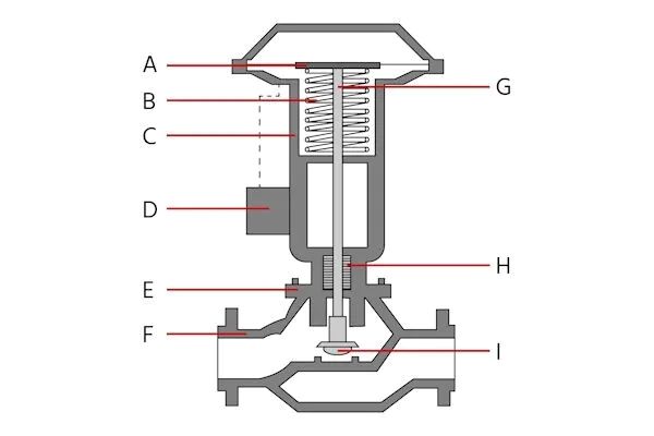
Actuator (A)
The actuator is the core component responsible for converting air pressure into mechanical motion. It can be a diaphragm actuator or piston actuator. Diaphragm actuators are suitable for low-pressure applications, while piston actuators are better for high-pressure environments. Actuators can be single-acting or double-acting, with the former relying on a spring return when air pressure is lost, while the latter provides bidirectional control without the need for a spring.
Spring (B)
In single-acting actuators, the spring acts as a fail-safe, returning the valve to a safe position if air pressure is lost.
Yoke (C)
The yoke connects the actuator to the valve body, ensuring proper alignment and stability, especially in high-pressure systems.
Positioner (D)
The positioner adjusts the actuator to set the valve in the desired position, sending feedback to the control system for accurate flow regulation. Positioners can be pneumatic, electro-pneumatic, or digital, with digital versions offering the highest precision.
Bonnet (E)
The bonnet is a protective housing that ensures a pressure-tight seal and allows for maintenance access to internal components.
Valve Body (F)
The valve body houses critical components like the valve seat and plug, influencing flow control capabilities. Valve bodies come in various types, such as globe, ball, butterfly, and gate valves, each suited for different applications.
Valve Stem (G)
The valve stem connects the actuator to internal components like the plug or disc, transmitting the actuator’s motion.
Seals and Gaskets (H)
Seals and gaskets are vital for preventing leaks at junctions, ensuring efficient operation and safety.
Valve Seat and Plug (I)
The valve seat and plug regulate flow by opening or closing, and their material selection is crucial for reliable sealing.
Despite their robust design, pneumatic control valves are prone to faults that can affect performance:
Air Leaks
Leaks in the supply line or valve assembly can impair actuator performance, causing sluggish valve movement or failure to respond.
Sticking or Jamming
Debris, rust, or corrosion can cause internal components to stick, leading to loss of control and efficiency.
Actuator Failure
Actuators may fail due to wear, air pressure loss, or physical damage, causing the valve to remain stuck in one position.
Positioner Malfunction
Miscalibrated or unresponsive positioners can lead to incorrect valve positioning, disrupting flow control.
Seal Wear and Leakage
Worn seals can cause leakage, reducing efficiency and posing safety risks.
Effective troubleshooting is essential for identifying and addressing issues with pneumatic control valves. Here are some key steps:
Review Maintenance Records
Check past maintenance logs to identify recurring issues that might provide insight into the current problem.
Visual Inspection
Inspect the valve, actuator, yoke, and bonnet for signs of wear, corrosion, or damage. Look for leaks, cracks, or mechanical stress.
Check Air Supply
Ensure the air pressure is within the required range and check for leaks or blockages in hoses and fittings.
Actuator Inspection
Test the actuator’s movement manually, checking for air leaks or unusual sounds that might indicate damage or a broken seal.
Positioner Calibration
Ensure the positioner is calibrated correctly and free from electrical faults, signal interference, or calibration errors.
Control Signal Verification
Verify that the control signals sent to the valve are accurate, checking for discrepancies that might indicate faulty wiring or interference.
Manual Operation Test
Manually operate the valve to check for smooth, consistent movement and listen for unusual noises.
Internal Component Inspection
If necessary, disassemble the valve to inspect internal components like the valve seat, stem, and plug for wear or debris.
Pipeline Inspection
Clean or replace pipeline sections showing signs of clogging or corrosion that may hinder valve operation.
Pneumatic control valves are crucial for automated industrial processes, ensuring reliable and precise fluid and gas flow control. Understanding the components, identifying common faults, and following effective troubleshooting techniques are vital for maintaining optimal valve performance. By staying proactive with maintenance and addressing issues promptly, industries can ensure the continued efficient operation of their pneumatic control systems.Know more about Google SEO Directory