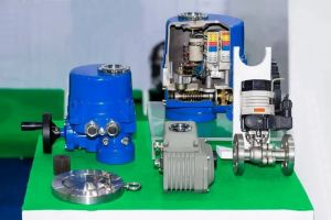


Maintaining Stroke Accuracy in Control Valves: Why Calibration Matters
As a leading control valves manufacturer in China, we provide premium valves and control actuators expertly designed to meet a wide range of industrial requirements.In industrial automation, control valves are vital for regulating flow, pressure, and temperature. However, extended use without maintenance often leads to valve stroke inaccuracies—where the valve fails to open to the intended position. This deviation can compromise system efficiency, stability, and safety.
The “stroke” of a control valve refers to the range of motion from fully closed (0%) to fully open (100%). Over time, factors like mechanical wear, vibration, and pressure variation can cause the valve’s actual position to diverge from the control signal. For example, a 50% command might result in a 40% or 60% opening, leading to process inconsistencies.
Regular calibration corrects these discrepancies. Technicians typically verify valve responsiveness at five key points: 0%, 25%, 50%, 75%, and 100%. These checkpoints help maintain linear and accurate control throughout the valve’s stroke.
Mechanical valve positioners—still widely used in industry—require manual calibration, relying on internal cams, springs, and feedback rods. Two key adjustments are needed: one for the zero point (fully closed at 4 mA) and another for the span (fully open at 20 mA).
Zero Adjustment: Apply a 4 mA signal. If the valve isn’t fully closed, adjust the zero screw until it is.
Mid-Point Check (50%): Send a 12 mA signal. If the valve opening isn’t accurate, adjust the span mechanism. Ensure the feedback rod is vertically aligned.
Full Stroke (100%): Apply 20 mA and confirm full opening. Re-adjust span if needed.
Verify Intermediate Points: Recheck at 25% and 75% to confirm proportional response. Fine-tune if necessary.
Mechanical Positioners
These offer rugged reliability and direct mechanical feedback, ideal for tough environments or cost-sensitive operations. They provide hands-on learning for new technicians, offering insight into valve dynamics and process behavior.
Intelligent Positioners
Modern systems use microprocessors and auto-calibration to simplify setup and reduce maintenance. They automatically adjust stroke range and provide real-time diagnostics. While easier to use, they still require technical knowledge for interpreting data and responding to alarms.
Whether mechanical or digital, valve positioners are the bridge between control signals and valve movement. If a positioner fails—due to signal loss, wear, or mechanical issues—the system may default to manual control or shut down, impacting production and safety.
Calibrate Regularly: Every 6–12 months depending on usage and environment.
Align Feedback Components: Prevent mechanical bias or wear from misalignment.
Avoid Over-Tightening: Prevent deformation of components during reassembly.
Use Built-In Diagnostics: Intelligent positioners often offer early fault detection.
Log Calibration Data: Useful for performance tracking and troubleshooting.
Both mechanical and intelligent positioners are essential tools for reliable process control. Mechanical systems offer robustness and training value, while intelligent ones deliver precision and efficiency. Regardless of type, accurate calibration ensures system reliability, safety, and optimal performance—keeping industrial processes running smoothly and minimizing costly downtime.
